< Intro To QOS & Winsock APIs | QOS Programming Main | QOS Programming >
Generic Quality of Service (QOS) 10 Part 2
What do we have in this chapter 10 part 2?
-
QOS and Winsock
-
QOS Structures
-
QOS
-
FLOWSPEC
-
TokenRate
-
TokenBucketSize
-
PeakBandwidth
-
Latency
-
DelayVariation
-
ServiceType
-
MaxSduSize
-
MinimumPolicedSize
-
QOS-Invoking Functions
-
WSAConnect()
-
WSAAccept()
-
WSAJoinLeaf()
-
WSAIoctl()
-
Terminating QOS
-
Provider-Specific Objects
-
QOS Shape Discard Mode
-
QOS Destination Address
-
RSVP Status Info
-
RSVP Reserve Info
-
RSVP_DEFAULT_STYLE
-
RSVP_FIXED_FILTER_STYLE
-
RSVP_WILDCARD_STYLE
-
RSVP_SHARED_EXPLICIT_STYLE
-
RSVP Policy Info
|
|
QOS and Winsock
In the previous section, we discussed the various components required for the success of an end-to-end QOS network. Now we'll turn our attention to Winsock 2, which is the API you use to programmatically access QOS from an application. First, we'll take a look at the top-level QOS structures that the majority of Winsock calls need. Next, we'll cover the Winsock functions capable of invoking QOS on a socket, as well as how to terminate QOS once it has been enabled on a socket. The last thing we'll do is cover the provider-specific objects that can be used to affect the behavior of, or return information from, the QOS service provider. It might seem a bit out of order to jump from a discussion of the major QOS structures to QOS functions and then back to provider-specific structures. However, we want to give a thorough, high-level overview of how the major structures interact with the Winsock API calls before delving into the details of the provider-specific options.
QOS Structures
The central structure in QOS programming is the QOS structure. This structure consists of:
QOS
The QOS structure specifies the QOS parameters for both sending and receiving traffic. It is defined as:
typedef struct _QualityOfService { FLOWSPEC SendingFlowspec; FLOWSPEC ReceivingFlowspec; WSABUF ProviderSpecific; } QOS, FAR * LPQOS; |
The FLOWSPEC structures define the traffic characteristics and requirements for each traffic direction, while the ProviderSpecific field is used to return information and to change the behavior of QOS. These provider-specific options are covered in detail a little later in this chapter.
FLOWSPEC
FLOWSPEC is the basic structure that describes a single flow. Remember that a flow describes data traveling in a single direction. The structure is defined as:
typedef struct _flowspec
{
ULONG TokenRate;
ULONG TokenBucketSize;
ULONG PeakBandwidth;
ULONG Latency;
ULONG DelayVariation;
SERVICETYPE ServiceType;
ULONG MaxSduSize;
ULONG MinimumPolicedSize;
} FLOWSPEC, *PFLOWSPEC, FAR *LPFLOWSPEC;
Let's take a look at the meaning of each of the FLOWSPEC structure fields.
TokenRate
The TokenRate field specifies the rate of transmission for data that is given in bytes per second. An application can transmit data at this rate, but if for some reason it transmits data at a lower rate, the application can accrue extra tokens so that more data can be transmitted later. However, the number of tokens that an application can accrue is bound by PeakBandwidth. This accumulation of token credits is limited by the TokenBucketSize field. By limiting the total number of tokens, we avoid a situation of inactive flows that have accrued many tokens, which could lead to flooding the available bandwidth. Because flows can accrue transmission credits over time (at their TokenRate value) only up to the maximum of their TokenBucketSize, and they are limited in “burst transmissions” to their PeakBandwidth, TC (Traffic Control) and network-device resource integrity are maintained. TC is maintained because flows cannot send too much data at once, and network-device resource integrity is maintained because such devices are spared high-traffic bursts.
Because of these limitations, an application can transmit only when sufficient credits have accrued. If the required number of credits are not available, the application must either wait until sufficient credits have accrued to send the data or discard the data altogether. The TC module determines what happens to data queued too long without being sent. Therefore, applications should take care to base their TokenRate requests on reasonable amounts. If an application does not require scheduling of transmission rates, this field can be set to QOS_NOT_SPECIFIED (-1).
TokenBucketSize
As we discussed earlier, the TokenBucketSize field limits the number of credits that can accrue for a given flow. For example, video applications would set this field to the frame size being transmitted because it is desirable to have single video frames being transmitted one at a time. Applications requiring a constant data rate should set this field to allow for some variation. Like the TokenRate field, TokenBucketSize is expressed in bytes per second.
PeakBandwidth
PeakBandwidth specifies the maximum amount of data transmitted in a given period of time. In effect, this value specifies the maximum amount of burst data. This is an important value because it prevents applications that have accrued a significant number of transmission tokens from flooding the network all at once. PeakBandwidth is expressed in bytes per second.
Latency
The Latency field specifies the maximum acceptable delay between the transmission of a bit and its receipt by the intended recipient or recipients. How this value is interpreted depends on the level of service requested in the ServiceType field. Latency is expressed in microseconds.
DelayVariation
DelayVariation specifies the difference between the minimum and maximum delay that a packet can experience. Typically, an application uses this value to determine the amount of buffer space required to receive the data and still maintain the original data transmission pattern. DelayVariation is expressed in microseconds.
ServiceType
The ServiceType field specifies the level of service that the data flow requires. The following service types can be specified:
- SERVICETYPE_NOTRAFFIC indicates that no data is being transmitted in this direction.
- SERVICETYPE_BESTEFFORT indicates that the parameters specified in FLOWSPEC are guidelines and that the system will make a reasonable effort to maintain that service level; however, there are no guarantees of packet delivery.
- SERVICETYPE_CONTROLLEDLOAD indicates that data transmission will closely approximate transmission quality provided by best-effort service on a network with non-loaded traffic conditions. This really breaks down into two conditions. First, packet loss will approximate the normal error rate of the transmission medium; and second, transmission delay will not greatly exceed the minimum delay that delivered packets experience.
- SERVICETYPE_GUARANTEED guarantees data transmission at the rate specified by the TokenRate field over the lifetime of the connection. However, if the data transmission rate exceeds TokenRate, data might be delayed or discarded (depending on how TC is configured). In addition, if TokenRate is not exceeded, Latency is also guaranteed.
- SERVICETYPE_QUALITATIVE behaves similarly to SERVICETYPE_ BESTEFFORT.
- SERVICETYPE_NETWORK_CONTROL has the highest priority and is typically used only for controlling the network. In general, you should not use this level.
In addition to these six service types, several other flags provide information that can be returned to an application. These informational flags can be ORed with any valid ServiceType flag. Table 10-1 lists these information flags.
|
Table 10-1 Service Type Modifier Flags
|
|
|
Value |
Meaning |
|
SERVICETYPE_NETWORK_UNAVAILABLE |
Indicates a loss of service in either the sending or the receiving direction. |
|
SERVICETYPE_GENERAL_INFORMATION |
Indicates that all service types are supported for a flow. |
|
SERVICETYPE_NOCHANGE |
Indicates that there is no change in the requested QOS service level. This flag can be returned from a Winsock call or an application can specify this flag when renegotiating QOS to indicate no change in the QOS levels for the given direction. |
|
SERVICETYPE_NONCONFORMING |
This flag is not used. |
|
SERVICE_NO_TRAFFIC_CONTROL |
This flag can be ORed with other ServiceType flags to disable TC altogether. |
|
SERVICE_NO_QOS_SIGNALING |
This flag prevents any RSVP signaling messages from being sent. Local TC will be invoked, but no RSVP Path messages will be sent. This flag can also be used in conjunction with a receiving FLOWSPEC structure to suppress the automatic generation of an RESV message. The application receives notification that a PATH message has arrived and then needs to alter the QOS by issuing WSAIoctl() (SIO_SET_QOS) to unset this flag and thereby cause RESV messages to go out. |
MaxSduSize
The MaxSduSize field indicates the maximum packet size for data transmitted in the given flow. MaxSduSize is expressed in bytes.
MinimumPolicedSize
The MinimumPolicedSize field indicates the minimum packet size that can be transmitted in the given flow. MinimumPolicedSize is expressed in bytes.
QOS-Invoking Functions
Let's say you want your application to make a request on the network for certain bandwidth requirements. Four functions initiate the process. Once an RSVP session has begun, an application can register for FD_QOS events. QOS status information and error codes are conveyed to applications as FD_QOS events. Applications can register to receive these events in the usual way: by including the FD_QOS flag in the event field of either the WSAAsyncSelect() function or the WSAEventSelect() function.
The FD_QOS notification is especially relevant if a connection is established that uses FLOWSPEC structures that specify default values (QOS_NOT_SPECIFIED). Once the application has made the request for QOS, the underlying provider will periodically update the FLOWSPEC structure to indicate current network conditions and will notify the application by posting an FD_QOS event. With this information, applications can request or modify QOS levels to reflect the amount of available bandwidth. Keep in mind that the updated information is an indication of the locally available bandwidth only and does not necessarily indicate the end-to-end bandwidth.
Once a flow is established, available network bandwidth might change or a single party taking part in an established flow might decide to change the requested QOS service level. A renegotiation of allocated resources generates an FD_QOS event to indicate the change to the application. At this point, the application should call SIO_GET_QOS to obtain the new resource levels. We'll revisit QOS event signaling and status information in the section on programming QOS later in this chapter.
WSAConnect()
A client uses the WSAConnect() function to initiate a unicast QOS connection to a server. WSAConnect() is defined as follows:
int WSAConnect (
SOCKET s,
const struct sockaddr FAR *name,
int namelen,
LPWSABUF lpCallerData,
LPWSABUF lpCalleeData,
LPQOS lpSQOS,
LPQOS lpGQOS
);
The requested QOS values are passed as the lpSQOS parameters. Currently, group QOS is not supported or implemented; a null value should be passed for lpGQOS.
The WSAConnect() call can be used with connection-oriented or connectionless sockets. With a connection-oriented socket, this function establishes the connection and also generates the appropriate PATH and/or RESV messages. For connectionless sockets, you must associate an endpoint's address with the socket so that the service provider knows where to send PATH and RESV messages. The caveat with using WSAConnect() on a connectionless socket is that only data sent to that destination address will be shaped by the system according to the QOS levels associated with that socket. In other words, if WSAConnect() is used to associate an endpoint on a connectionless socket, data can be transferred only between those two endpoints for the lifetime of the socket. If you need to send data with QOS guarantees to multiple endpoints, use WSAIoctl() and SIO_SET_QOS to specify each new endpoint.
WSAAccept()
The WSAAccept() function accepts a client connection that can be QOS-enabled. The prototype for the function is as follows:
SOCKET WSAAccept(
SOCKET s,
struct sockaddr FAR *addr,
LPINT addrlen,
LPCONDITIONPROC lpfnCondition,
DWORD dwCallbackData
);
If you want to supply a conditional function, you must prototype it as:
int CALLBACK ConditionalFunc(
LPWSABUF lpCallerId,
LPWSABUF lpCallerData,
LPQOS lpSQOS,
LPQOS lpGQOS,
LPWSABUF lpCalleeId,
LPWSABUF lpCalleeData,
GROUP FAR *g,
DWORD dwCallbackData
);
The drawback is that the QOS service provider does not guarantee to return the actual QOS values that the client requests as the lpSQOS parameter, so to enable QOS on the client socket, WSAIoctl() with SIO_SET_QOS must be called before or after WSAAccept(). If QOS is set on the listening socket, those values will be copied over to the client socket by default.
Unfortunately, the QOS service provider will not pass valid QOS parameters into the conditional function even if a PATH message has already arrived. Basically, don't use the WSAAccept() condition function.
There is one issue to be aware of when using WSAAccept() in Windows 98 and Windows Me. If you use a conditional function with WSAAccept() and the lpSQOS parameter is not null, you must set QOS (using SIO_SET_QOS), or WSAAccept() will fail.
WSAJoinLeaf()
WSAJoinLeaf() is used for multipoint communications. The function is defined as:
SOCKET WSAJoinLeaf(
SOCKET s,
const struct sockaddr FAR *name,
int namelen,
LPWSABUF lpCallerData,
LPWSABUF lpCalleeData,
LPQOS lpSQOS,
LPQOS lpGQOS,
DWORD dwFlags
);
For an application to join a multicast session, it must create a socket that has the appropriate flags (WSA_FLAG_MULTIPOINT_C_ROOT, WSA_FLAG_MULTIPOINT_C_LEAF, WSA_FLAG_MULTIPOINT_D_ROOT, and WSA_FLAG_MULTIPOINT_D_LEAF). When the application sets up multipoint communications, it specifies QOS parameters in the lpSQOS parameter.
When you use WSAJoinLeaf() to join IP multicast groups, the operation of joining a multicast group is separate from the QOS RSVP session setup. In fact, joining a multicast group is likely to succeed. The function returns without the reservation request completing. At some later time, you will receive an FD_QOS event that will notify you of either a success or a failure in allocating the requested resources.
Keep in mind the TTL set on multicast data. If you plan on setting the TTL with either SIO_MULTICAST_SCOPE or IP_MULTICAST_TTL, it must be set prior to calling WSAJoinLeaf() or calling the SIO_SET_QOS ioctl command to set QOS on the socket. If the scope is set after the QOS is already set, the TTL will not take effect until QOS is renegotiated through SIO_SET_QOS. The TTL value set will also be carried by the RSVP request.
Setting the TTL before setting QOS on a socket is important because the multicast TTL set on the socket also affects the TTL of the RSVP messages, which directly affects how many networks your resource reservation request is propagated to. For example, if you want to set up several endpoints in an IP multicast group that spans three networks, you ideally would set the TTL to 3 so that the network traffic you generate is not propagated to networks beyond those interested in the data. If the TTL isn't set before WSAJoinLeaf() is called, RSVP messages are sent out with a default TTL of 63, which results in the host attempting to reserve resources on far too many networks.
WSAIoctl()
The WSAIoctl() function with the ioctl option SIO_SET_QOS can be used either to request QOS for the first time on either a connected or an unconnected socket or to renegotiate QOS requirements after an initial QOS request. The one advantage to using WSAIoctl() is that if the QOS request fails, more detailed error information is returned via the provider-specific information.
The SIO_SET_QOS option is used to set or modify QOS parameters on a socket. One feature of using WSAIoctl() with SIO_SET_QOS is the capability to specify provider-specific objects to further refine QOS's behavior. The next section is dedicated to covering all of the provider-specific objects. In particular, if an application using connectionless sockets does not want to use WSAConnect(), it can call WSAIoctl() with SIO_SET_QOS and specify the destination address object in the provider-specific buffer to associate an endpoint so that an RSVP session can be established. When setting QOS parameters, pass the QOS structure as lpvInBuffer, with cbInBuffer indicating the amount of bytes passed in.
The SIO_GET_QOS option is used upon receipt of an FD_QOS event. When an application receives this event notification, a call to WSAIoctl() with SIO_GET_QOS should be made to investigate the reason. As we mentioned earlier, the FD_QOS event can be generated because of a change in the available bandwidth on the network or by renegotiation by the peer. To obtain the QOS values for a socket, pass a sufficiently large buffer as lpvOutBuffer, with cbOutBuffer indicating the size. The input parameters can be NULL and 0. The one tricky part of calling SIO_GET_QOS is passing a buffer large enough to hold the QOS structure, including the provider-specific objects. The ProviderSpecific field, a WSABUF structure, is within the QOS structure. If the len field is set to zero and the buf field is null, len will be updated with the necessary size upon return from WSAIoctl(). In addition, if the call fails because the buffer is too small, the len field will be updated with the correct size. Querying for the buffer size is supported only in Windows 2000 and Windows XP. For Windows 98 and Windows Me, you must always supply a large enough buffer, simply pick a large buffer size and stick with it.
Another ioctl command can be used with WSAIoctl(): SIO_CHK_QOS. This command can be used to query for the six values described in Table 10-2. When you call this command, the lpvInBuffer parameter points to a DWORD that is set to one of the three flags. The lpvOutBuffer parameter should also point to a DWORD, and upon return, the value requested is returned. The most commonly used flag is ALLOWED_TO_SEND_DATA. This flag is used by senders who have initiated a PATH message but have not received any RESV messages indicating successful allocation of the QOS level. When senders use the SIO_CHK_QOS ioctl command with the ALLOWED_TO_SEND_DATA flag, the network is queried to see whether the best-effort traffic currently available is sufficient for sending the kind of data described in the QOS structure passed to a QOS-invoking function.
|
Table 10-2 SIO_CHK_QOS Flags
|
||
|
SIO_CHK_QOS Flag |
Description |
Return Value |
|
ALLOWED_TO_SEND_DATA |
Indicates whether sending data can begin immediately or whether the application should wait for an RESV message |
BOOL |
|
ABLE_TO_RECV_RSVP |
Indicates to senders whether its interface is RSVP-enabled |
BOOL |
|
LINE_RATE |
Returns the bandwidth capacity of the interface |
DWORD |
|
LOCAL_TRAFFIC_CONTROL |
Returns whether TC is installed and available for use |
BOOL |
|
LOCAL_QOSABILITY |
Returns whether QOS is available |
BOOL |
|
END_TO_END_QOSABILITY |
Determines whether end-to-end QOS is available on the network |
BOOL |
The options listed in Table 10-2 that return BOOL values actually return 1 or 0 to indicate a yes or a no answer, respectively. The last four options in the table can return the constant INFO_NOT_AVAILABLE if the system cannot currently obtain the answer.
Terminating QOS
In the previous section, you learned how to invoke QOS on a socket. Next, we'll examine the termination of QOS guarantees. Each of the following events causes a termination of RSVP and TC processing for a socket.
- Closing a socket via the closesocket function.
- Shutting down a socket via the shutdown function.
- Calling WSAConnect() with a null peer address.
- Calling WSAIoctl() and SIO_SET_QOS with the SERVICETYPE_ NOTRAFFIC or the SERVICETYPE_BESTEFFORT service type.
Except for the second item in the list, these events are self-explanatory. Remember that the shutdown function can signal the cessation of either sending or receiving data, which will result in the termination of the flow of data for only that direction. In other words, if shutdown is called with SD_SEND, QOS will still be in effect for data being received.
Provider-Specific Objects
The provider-specific objects covered in this section are passed as part of the ProviderSpecific field of the QOS structure. Either they return QOS information to your application via the FD_QOS event or you can pass them along with the other QOS parameters to a WSAIoctl() call with the SIO_SET_QOS option to refine QOS's behavior.
Every provider-specific object contains a QOS_OBJECT_HDR structure as its first member. This structure identifies the type of provider-specific object. This is necessary because these provider objects are most commonly returned within the QOS structure after a call to SIO_GET_QOS. By using the QOS_ OBJECT_HDR, your application can identify each object and decode its significance. The object header is defined as:
typedef struct
{
ULONG ObjectType;
ULONG ObjectLength;
} QOS_OBJECT_HDR, *LPQOS_OBJECT_HDR;
ObjectType identifies the type of preset provider-specific object, while ObjectLength tells how long the entire object is, including the object header and the provider-specific object. An object type can be one of the flags listed in Table 10-3.
|
Table 10-3 Object Types
|
|
|
Provider Object |
Object Structure |
|
QOS_OBJECT_SD_MODE |
QOS_SD_MODE |
|
QOS_OBJECT_SHAPING_RATE |
QOS_SHAPING_RATE |
|
QOS_OBJECT_DESTADDR |
QOS_DESTADDR |
|
RSVP_OBJECT_STATUS_INFO |
RSVP_STATUS_INFO |
|
RSVP_OBJECT_RESERVE_INFO |
RSVP_RESERVE_INFO |
|
RSVP_OBJECT_ADSPEC |
RSVP_ADSPEC |
|
RSVP_OBJECT_POLICY_INFO |
RSVP_POLICY_INFO |
|
QOS_OBJECT_END_OF_LIST |
None. No more objects. |
QOS Shape Discard Mode
This QOS object defines how the Packet Shaper element of TC processes the data of a given flow. This property most often comes into play when dealing with flows that do not conform to the parameters given in FLOWSPEC. That is, if an application is sending data at a rate faster than what is specified in the TokenRate field of the sending FLOWSPEC, it is considered nonconforming. This object defines how the local system handles this occurrence. The QOS_SD_MODE structure is defined as:
typedef struct _QOS_SD_MODE
{
QOS_OBJECT_HDR ObjectHdr;
ULONG ShapeDiscardMode;
} QOS_SD_MODE, *LPQOS_SD_MODE;
The ShapeDiscardMode field can be one of the values specified in Table 10-4.
|
Table 10-4 QOS Shape DiscardMode Flags
|
|
|
Flag |
Description |
|
TC_NONCONF_BORROW |
The flow receives the resources remaining after all higher-priority flows have been serviced. Flows of this type are not subjected to either the Shaper or the Sequencer. If a value for TokenRate is specified, packets can be nonconforming and will be demoted to less than best-effort priority. |
|
TC_NONCONF_BORROW_PLUS |
Similar to TC_NONCONF_BORROW, however, packets will not be marked as nonconforming in the Shaper. |
|
TC_NONCONF_SHAPE |
A value for TokenRate must be specified. Nonconforming packets will be retained in the Packet Shaper until they become conforming. |
|
TC_NONCONF_DISCARD |
A value for TokenRate must be specified. Nonconforming packets will be discarded. |
You might wonder why you would want to use the TC_NONCONF_ DISCARD mode when it might result in dropping data before it even gets sent on the wire. One such use is in sending audio or video data. In most cases, the FLOWSPEC structure is set up to reflect sending a packet whose size is equal to one frame of video or a small segment of audio. If for some reason the packet does not conform, is it better for an application to wait until it does conform (as is the case with TC_NONCONF_SHAPE), or should the application drop the packet altogether and move on to the next one? For time-critical data such as video, it is often better to drop the frame and move on.
QOS Destination Address
The QOS_DESTADDR structure is used to specify the destination address for a connectionless sending socket without using a WSAConnect() call. No RSVP PATH or RESV messages will be sent until the destination address of a connectionless socket is known. The destination address can be set with the SIO_SET_QOS ioctl command. The structure is defined as:
typedef struct _QOS_DESTADDR
{
QOS_OBJECT_HDR ObjectHdr;
const struct sockaddr *SocketAddress;
ULONG SocketAddressLength;
} QOS_DESTADDR, *LPQOS_DESTADDR;
The SocketAddress field references the SOCKADDR structure that defines the endpoint's address for the given protocol. SocketAddressLength is simply the size of the SOCKADDR structure.
RSVP Status Info
The RSVP status info object is used to return RSVP-specific error and status information. The structure is defined as:
typedef struct _RSVP_STATUS_INFO {
QOS_OBJECT_HDR ObjectHdr;
ULONG StatusCode;
ULONG ExtendedStatus1;
ULONG ExtendedStatus2;
} RSVP_STATUS_INFO, *LPRSVP_STATUS_INFO;
The StatusCode field is the RSVP message returned. The possible codes are described in Table 10-5. The other two fields, ExtendedStatus1 and ExtendedStatus2, are reserved for provider-specific information.
|
Table 10-5 RSVP Status Info Codes
|
|
|
Flag |
Meaning |
|
WSA_QOS_RECEIVERS |
At least one RESV message has arrived. |
|
WSA_QOS_SENDERS |
At least one PATH message has arrived. |
|
WSA_QOS_NO_RECEIVERS |
There are no receivers. |
|
WSA_QOS_NO_SENDERS |
There are no senders. |
|
WSA_QOS_REQUEST_CONFIRMED |
The reserve has been confirmed. |
|
WSA_QOS_ADMISSION_FAILURE |
Request failed due to lack of resources. |
|
WSA_QOS_POLICY_FAILURE |
Request rejected for administrative reasons or bad credentials. |
|
WSA_QOS_BAD_STYLE |
Unknown or conflicting style. |
|
WSA_QOS_BAD_OBJECT |
There is a problem with some part of the RSVP_FILTERSPEC structure or with the provider-specific buffer in general. (This object will be discussed shortly.) |
|
WSA_QOS_TRAFFIC_CTRL_ERROR |
There is a problem with some part of the FLOWSPEC structure. |
|
WSA_QOS_GENERIC_ERROR |
General error. |
|
ERROR_IO_PENDING |
Overlapped operation is canceled. |
Typically, an application receives an FD_QOS event and calls SIO_ GET_QOS to obtain a QOS structure containing an RSVP_STATUS_INFO object when an RSVP message is received. For example, for a QOS-enabled UDP-based receiver, an FD_QOS event containing a WSA_QOS_SENDERS message is generated to indicate that someone has requested the QOS service to send data to the receiver.
RSVP Reserve Info
The RSVP reserve info object is used for storing RSVP-specific information for fine-tuning interactions via the Winsock 2 QOS APIs and the provider-specific buffer. An RSVP_RESERVE_INFO object overrides the default reservation style and is used by a QOS receiver. The object is defined as:
typedef struct _RSVP_RESERVE_INFO
{
QOS_OBJECT_HDR ObjectHdr;
ULONG Style;
ULONG ConfirmRequest;
LPRSVP_POLICY_INFO PolicyElementList;
ULONG NumFlowDesc;
LPFLOWDESCRIPTOR FlowDescList;
} RSVP_RESERVE_INFO, *LPRSVP_RESERVE_INFO;
The Style field specifies the filter type that should be applied to this receiver. Table 10-6 lists the filter types available and the default filter types that different types of receivers use.
|
Table 10-6 Default Filter Styles
|
|
|
Filter Style |
Default Users |
|
Fixed filter |
Unicast receivers; connected UDP receivers |
|
Wildcard |
Multicast receivers; unconnected UDP receivers |
|
Shared explicit |
None |
Each filter style will be discussed in greater detail shortly. If the ConfirmRequest field is nonzero, notification will be sent once the RESV request has been received for receiving applications. NumPolicyElement is related to the PolicyElementList field. PolicyElementList is a list of RSVP_POLICY objects that we define a little bit later in this chapter. Let's take a look at the different filter styles and the characteristics of each.
RSVP_DEFAULT_STYLE
This flag tells the QOS service provider to use the default style. Table 10-6 lists the default styles for the different possible receivers. Unicast receivers use fixed filter, whereas wildcard is for multicast receivers. UDP receivers that call WSAConnect() also use fixed filter.
RSVP_FIXED_FILTER_STYLE
Normally, this style establishes a single flow with QOS guarantees between the receiver and a single source. This is the case for a unicast receiver and connected UDP receivers: NumFlowDesc is set to 1, and FlowDescList contains the sender's address. However, it is also possible to set up a multiple fixed filter style that allows a receiver to reserve mutually exclusive flows from multiple, explicitly identified sources. For example, if your receiver intends to receive data from three senders and needs guaranteed bandwidth of 20 Kbps for each, use the multiple fixed filter style. In this example, NumFlowDesc is set to 3, while FlowDescList contains three addresses, one for each FLOWSPEC. It is also possible to assign varying levels of QOS to each sender; they do not all have to be equal. Note that unicast receivers and connected UDP receivers cannot use multiple fixed filters. Figure 10-1 shows the relationship between FLOWDESCRIPTOR and RSVP_FILTERSPEC structures.
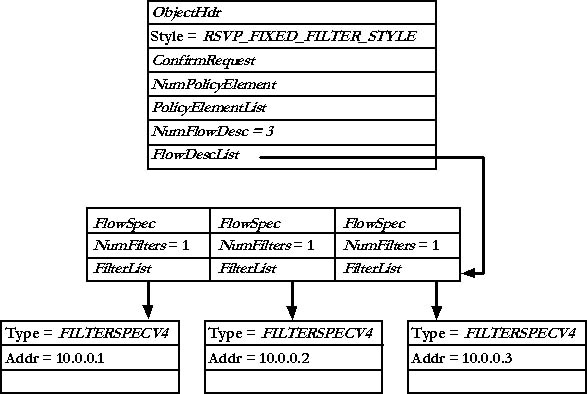
Figure 10-1 Multiple fixed filter style
RSVP_WILDCARD_STYLE
Multicast receivers and unconnected UDP receivers use the wildcard style. To use this style for TCP connections or for connected UDP receivers, set NumFlowDesc to 0 and FlowDescList to NULL. This is the default filter style for unconnected UDP receivers and multicast applications because the sender's address is unknown.
RSVP_SHARED_EXPLICIT_STYLE
This style is somewhat similar to multiple fixed filter style except that network resources are shared among all senders instead of being allocated for each sender. In this case, NumFlowDesc is 1 and FlowDescList contains the list of sender addresses. Figure 10-2 illustrates this style.

Figure 10-2 Shared explicit style
We've introduced the last two fields, NumFlowDesc and FlowDescList, in our discussion of RSVP styles. How you use these two fields depends on the style. NumFlowDesc defines the number of FLOWDESCRIPTOR objects in the FlowDescList field. This structure is defined as:
typedef struct _FLOWDESCRIPTOR
{
FLOWSPEC FlowSpec;
ULONG NumFilters;
LPRSVP_FILTERSPEC FilterList;
} FLOWDESCRIPTOR, *LPFLOWDESCRIPTOR;
This object is used to define the types of filters per FLOWSPEC given by FlowSpec. Again, the NumFilters field contains the number of RSVP_FILTERSPEC objects present in the FilterList array. The RSVP_FILTERSPEC object is defined as:
typedef struct _RSVP_FILTERSPEC {
FilterType Type;
union {
RSVP_FILTERSPEC_V4 FilterSpecV4;
RSVP_FILTERSPEC_V6 FilterSpecV6;
RSVP_FILTERSPEC_V6_FLOW FilterSpecV6Flow;
RSVP_FILTERSPEC_V4_GPI FilterSpecV4Gpi;
RSVP_FILTERSPEC_V6_GPI FilterSpecV6Gpi;
};
} RSVP_FILTERSPEC, *LPRSVP_FILTERSPEC;
The first field, Type, is a simple enumeration of the following values:
typedef enum {
FILTERSPECV4 = 1,
FILTERSPECV6,
FILTERSPECV6_FLOW,
FILTERSPECV4_GPI,
FILTERSPECV6_GPI,
FILTERSPEC_END
} FilterType;
This enumeration specifies the object present in the union. Each of these filter specs is defined as follows:
typedef struct _RSVP_FILTERSPEC_V4 {
IN_ADDR_IPV4 Address;
USHORT Unused;
USHORT Port;
} RSVP_FILTERSPEC_V4, *LPRSVP_FILTERSPEC_V4;
typedef struct _RSVP_FILTERSPEC_V6 {
IN_ADDR_IPV6 Address;
USHORT UnUsed;
USHORT Port;
} RSVP_FILTERSPEC_V6, *LPRSVP_FILTERSPEC_V6;
typedef struct _RSVP_FILTERSPEC_V6_FLOW {
IN_ADDR_IPV6 Address;
UCHAR UnUsed;
UCHAR FlowLabel[3];
} RSVP_FILTERSPEC_V6_FLOW, *LPRSVP_FILTERSPEC_V6_FLOW;
typedef struct _RSVP_FILTERSPEC_V4_GPI {
IN_ADDR_IPV4 Address;
ULONG GeneralPortId;
} RSVP_FILTERSPEC_V4_GPI, *LPRSVP_FILTERSPEC_V4_GPI;
typedef struct _RSVP_FILTERSPEC_V6_GPI {
IN_ADDR_IPV6 Address;
ULONG GeneralPortId;
} RSVP_FILTERSPEC_V6_GPI, *LPRSVP_FILTERSPEC_V6_GPI;
RSVP Adspec
The RSVP_ADSPEC object defines the information carried in the RSVP Adspec. This RSVP object typically indicates which service types are available (controlled load or guaranteed), whether a non-RSVP hop has been encountered by the PATH message, and the minimum MTU along the path. The structure is defined as:
typedef struct _RSVP_ADSPEC
{
QOS_OBJECT_HDR ObjectHdr;
AD_GENERAL_PARAMS GeneralParams;
ULONG NumberOfServices;
CONTROL_SERVICE Services[1];
} RSVP_ADSPEC, *LPRSVP_ADSPEC;
The first field of interest is GeneralParams, which is a structure of type AD_GENERAL_PARAMS. This structure is exactly as it sounds, it defines some general characterization parameters. The definition of this object is:
typedef struct _AD_GENERAL_PARAMS
{
ULONG IntServAwareHopCount;
ULONG PathBandwidthEstimate;
ULONG MinimumLatency;
ULONG PathMTU;
ULONG Flags;
} AD_GENERAL_PARAMS, *LPAD_GENERAL_PARAMS;
The IntServAwareHopCount is the number of hops that conform to Integrated Services (IntServ) requirements. PathBandwidthEstimate is the minimum bandwidth available from sender to receiver. MinimumLatency is the sum of minimum latencies, in microseconds, of the packet forwarding processes in the routers. PathMTU is the maximum transmission unit, end-to-end, that will not incur any fragmentation. The Flags field is not used anymore.
RSVP Policy Info
The last provider object we'll take a look at is the RSVP policy info. This object is rather nebulous—it contains any number of policy elements from RSVP that are not defined. The structure is defined as:
typedef struct _RSVP_POLICY_INFO {
QOS_OBJECT_HDR ObjectHdr;
ULONG NumPolicyElement;
RSVP_POLICY PolicyElement[1];
} RSVP_POLICY_INFO, *LPRSVP_POLICY_INFO;
The NumPolicyElement field gives the number of RSVP_POLICY structures present in the PolicyElement array. This structure is defined as:
typedef struct _RSVP_POLICY {
USHORT Len;
USHORT Type;
UCHAR Info[4];
} RSVP_POLICY, *LPRSVP_POLICY;
The RSVP_POLICY structure is data transported by RSVP on behalf of the policy component and is not particularly relevant to our needs.
Related reference:
< Intro To QOS & Winsock APIs | QOS Programming Main | QOS Programming >